Let us turn to a more detailed consideration of the refractive index introduced by us in § 81 when formulating the law of refraction.
The refractive index depends on the optical properties and the medium from which the beam falls and the medium into which it penetrates. The refractive index obtained when light from a vacuum falls on a medium is called the absolute refractive index of this medium.
Rice. 184. Relative refractive index of two media:
![]()
Let the absolute refractive index of the first medium be and the second medium - . Considering the refraction at the boundary of the first and second media, we make sure that the refractive index during the transition from the first medium to the second, the so-called relative refractive index, is equal to the ratio of the absolute refractive indices of the second and first media:
(Fig. 184). On the contrary, when passing from the second medium to the first, we have a relative refractive index
The established connection between the relative refractive index of two media and their absolute refractive indices could also be derived theoretically, without new experiments, just as it can be done for the law of reversibility (§82),
A medium with a higher refractive index is said to be optically denser. The refractive index of various media relative to air is usually measured. The absolute refractive index of air is . Thus, the absolute refractive index of any medium is related to its refractive index relative to air by the formula
Table 6. Refractive index of various substances relative to air
The refractive index depends on the wavelength of light, that is, on its color. Different colors correspond to different refractive indices. This phenomenon, called dispersion, plays important role in optics. We will deal with this phenomenon repeatedly in later chapters. The data given in table. 6, refer to yellow light.
It is interesting to note that the law of reflection can be formally written in the same form as the law of refraction. Recall that we agreed to always measure the angles from the perpendicular to the corresponding ray. Therefore, we must consider the angle of incidence and the angle of reflection to have opposite signs, i.e. the law of reflection can be written as
Comparing (83.4) with the law of refraction, we see that the law of reflection can be considered as a special case of the law of refraction at . This formal similarity between the laws of reflection and refraction is of great use in solving practical problems.
In the previous presentation, the refractive index had the meaning of a constant of the medium, independent of the intensity of the light passing through it. Such an interpretation of the refractive index is quite natural; however, in the case of high radiation intensities achievable using modern lasers, it is not justified. properties of the medium through which the strong light emission, in this case depend on its intensity. As they say, the medium becomes non-linear. The nonlinearity of the medium manifests itself, in particular, in the fact that a light wave of high intensity changes the refractive index. The dependence of the refractive index on the radiation intensity has the form
Here, is the usual refractive index, a is the non-linear refractive index, and is the proportionality factor. The additional term in this formula can be either positive or negative.
The relative changes in the refractive index are relatively small. At ![]() non-linear refractive index. However, even such small changes in the refractive index are noticeable: they manifest themselves in a peculiar phenomenon of self-focusing of light.
non-linear refractive index. However, even such small changes in the refractive index are noticeable: they manifest themselves in a peculiar phenomenon of self-focusing of light.
Consider a medium with a positive nonlinear refractive index. In this case, the areas of increased light intensity are simultaneous areas of increased refractive index. Usually, in real laser radiation, the intensity distribution over the cross section of the beam is nonuniform: the intensity is maximum along the axis and smoothly decreases towards the edges of the beam, as shown in Fig. 185 solid curves. A similar distribution also describes the change in the refractive index over the cross section of a cell with a nonlinear medium, along the axis of which the laser beam propagates. The refractive index, which is greatest along the cell axis, gradually decreases towards its walls (dashed curves in Fig. 185).
A beam of rays emerging from the laser parallel to the axis, falling into a medium with a variable refractive index, is deflected in the direction where it is greater. Therefore, an increased intensity in the vicinity of the OSP cell leads to a concentration of light rays in this region, which is shown schematically in cross sections and in Fig. 185, and this leads to a further increase in . Ultimately, the effective cross section of a light beam passing through a nonlinear medium decreases significantly. Light passes as if through a narrow channel with an increased refractive index. Thus, the laser beam narrows, and the nonlinear medium acts as a converging lens under the action of intense radiation. This phenomenon is called self-focusing. It can be observed, for example, in liquid nitrobenzene.

Rice. 185. Distribution of radiation intensity and refractive index over the cross section of the laser beam of rays at the entrance to the cuvette (a), near the input end (), in the middle (), near the output end of the cuvette ()
Determination of the refractive index of transparent solids
And liquids
Instruments and accessories: a microscope with a light filter, a plane-parallel plate with an AB mark in the form of a cross; refractometer brand "RL"; set of liquids.
Goal of the work: determine the refractive indices of glass and liquids.
Determination of the refractive index of glass using a microscope
To determine the refractive index of a transparent solid, a plane-parallel plate made of this material with a mark is used.
The mark consists of two mutually perpendicular scratches, one of which (A) is applied to the bottom, and the second (B) - to the top surface of the plate. The plate is illuminated with monochromatic light and examined under a microscope. On
rice. 4.7 shows a section of the investigated plate by a vertical plane.
Rays AD and AE after refraction at the glass-air interface go in the directions DD1 and EE1 and fall into the microscope objective.
An observer who looks at the plate from above sees point A at the intersection of the continuation of the rays DD1 and EE1, i.e. at point C.
Thus, point A seems to the observer located at point C. Let's find the relationship between the refractive index n of the plate material, the thickness d and the apparent thickness d1 of the plate.
4.7 it can be seen that VD \u003d BCtgi, BD \u003d ABtgr, from where
tgi/tgr = AB/BC,
where AB = d is the plate thickness; BC = d1 apparent plate thickness.
If angles i and r are small, then
Sini/Sinr = tgi/tgr, (4.5)
those. Sini/Sinr = d/d1.
Taking into account the law of light refraction, we obtain
The measurement of d/d1 is made using a microscope.
The optical scheme of the microscope consists of two systems: an observation system, which includes an objective and an eyepiece mounted in a tube, and an illumination system, consisting of a mirror and a removable light filter. Image focusing is carried out by rotating the handles located on both sides of the tube.
On the axis of the right handle there is a disk with a limb scale.
The reading b on the limb relative to the fixed pointer determines the distance h from the objective to the microscope stage:
The coefficient k indicates to what height the microscope tube moves when the handle is rotated by 1°.
The diameter of the objective in this setup is small compared to the distance h, so the outermost beam that enters the objective forms a small angle i with the optical axis of the microscope.
The angle of refraction r of light in the plate is less than the angle i, i.e. is also small, which corresponds to condition (4.5).
Work order
1. Put the plate on the microscope stage so that the point of intersection of strokes A and B (see Fig.
Refractive index
4.7) was in the field of view.
2. Rotate the handle of the lifting mechanism to raise the tube to the top position.
3. Looking into the eyepiece, slowly lower the microscope tube by rotating the handle until a clear image of scratch B, applied to the upper surface of the plate, is obtained in the field of view. Record the indication b1 of the limb, which is proportional to the distance h1 from the microscope objective to the top edge of the plate: h1 = kb1 (Fig.
4. Continue lowering the tube smoothly until a clear image of scratch A is obtained, which seems to the observer located at point C. Record a new reading b2 of the limbus. The distance h1 from the objective to the upper surface of the plate is proportional to b2:
h2 = kb2 (Fig. 4.8, b).
The distances from points B and C to the lens are equal, since the observer sees them equally clearly.
The displacement of the tube h1-h2 is equal to the apparent thickness of the plate (Fig.
d1 = h1-h2 = (b1-b2)k. (4.8)
5. Measure the plate thickness d at the intersection of the strokes. To do this, place an auxiliary glass plate 2 under the test plate 1 (Fig. 4.9) and lower the microscope tube until the lens touches (slightly) the test plate. Notice the indication of the limb a1. Remove the plate under study and lower the tube of the microscope until the objective touches the plate 2.
Note indication a2.
At the same time, the microscope objective will drop to a height equal to the thickness of the plate under study, i.e.
d = (a1-a2)k. (4.9)
6. Calculate the refractive index of the plate material using the formula
n = d/d1 = (a1-a2)/(b1-b2). (4.10)
7. Repeat all the above measurements 3-5 times, calculate the average value n, absolute and relative errors rn and rn/n.
Determination of the refractive index of liquids using a refractometer
Instruments that are used to determine the refractive indices are called refractometers.
General view and optical design RL refractometer are shown in fig. 4.10 and 4.11.
The measurement of the refractive index of liquids using a RL refractometer is based on the phenomenon of refraction of light that has passed through the interface between two media with different indicators refraction.
Light beam (Fig.
4.11) from a source 1 (an incandescent lamp or diffused daylight) with the help of a mirror 2 is directed through a window in the instrument housing onto a double prism consisting of prisms 3 and 4, which are made of glass with a refractive index of 1.540.
Surface AA of the upper illumination prism 3 (Fig.
4.12, a) is matte and serves to illuminate the liquid with scattered light, deposited in a thin layer in the gap between prisms 3 and 4. The light scattered by the matte surface 3 passes through a plane-parallel layer of the liquid under study and falls on the diagonal face of the explosive of the lower prism 4 under different
angles i ranging from zero to 90°.
To avoid the phenomenon of total internal reflection of light on the explosive surface, the refractive index of the investigated liquid should be less than the refractive index of the glass of prism 4, i.e.
less than 1,540.
A beam of light with an angle of incidence of 90° is called a gliding beam.
The sliding beam, refracted at the liquid-glass interface, will go in prism 4 at the limiting angle of refraction r etc< 90о.
The refraction of a sliding beam at point D (see Figure 4.12, a) obeys the law
nst / nzh \u003d sinipr / sinrpr (4.11)
or nzh = nstsinrpr, (4.12)
since sinipr = 1.
On the surface BC of prism 4, light rays are re-refracted and then
Sini¢pr/sinr¢pr = 1/ nst, (4.13)
r¢pr+i¢pr = i¢pr =a , (4.14)
where a is the refracting beam of the prism 4.
Solving together the system of equations (4.12), (4.13), (4.14), we can obtain a formula that relates the refractive index nzh of the liquid under study with the limiting angle of refraction r'pr of the beam that emerged from the prism 4:
If a spotting scope is placed in the path of the rays emerging from prism 4, then the lower part of its field of view will be illuminated, and the upper part dark. The interface between light and dark fields is formed by rays with a limiting refraction angle r¢pr. There are no rays with an angle of refraction smaller than r¢pr in this system (Fig.
The value of r¢pr, therefore, and the position of the chiaroscuro boundary depend only on the refractive index nzh of the liquid under study, since nst and a are constant values in this device.
Knowing nst, a and r¢pr, it is possible to calculate nzh using formula (4.15). In practice, formula (4.15) is used to calibrate the refractometer scale.
On scale 9 (see
rice. 4.11), the values of the refractive index for ld = 5893 Å are plotted on the left. In front of the eyepiece 10 - 11 there is a plate 8 with a mark (--).
By moving the eyepiece along with plate 8 along the scale, it is possible to achieve alignment of the mark with the dividing line between the dark and light fields of view.
The division of the graduated scale 9, coinciding with the mark, gives the value of the refractive index nzh of the liquid under study. Objective 6 and eyepiece 10-11 form a telescope.
Rotary prism 7 changes the course of the beam, directing it into the eyepiece.
Due to the dispersion of glass and the liquid under study, instead of a clear dividing line between dark and bright fields, when observed in white light, an iridescent stripe is obtained. To eliminate this effect, the dispersion compensator 5 is installed in front of the telescope lens. The main part of the compensator is a prism, which is glued from three prisms and can rotate relative to the axis of the telescope.
The refractive angles of the prism and their material are chosen so that yellow light with a wavelength ld = 5893 Å passes through them without refraction. If a compensatory prism is installed on the path of colored rays so that its dispersion is equal in magnitude, but opposite in sign to the dispersion of the measuring prism and the liquid, then the total dispersion will be equal to zero. In this case, the beam of light rays will gather into a white beam, the direction of which coincides with the direction of the limiting yellow beam.
Thus, when the compensatory prism rotates, the color of the color shade is eliminated. Together with the prism 5, the dispersion limb 12 rotates relative to the fixed pointer (see Fig. 4.10). The rotation angle Z of the limb makes it possible to judge the value of the average dispersion of the investigated liquid.
The dial scale must be graduated. The schedule is attached to the installation.
Work order
1. Raise the prism 3, place 2-3 drops of the test liquid on the surface of the prism 4 and lower the prism 3 (see Fig. 4.10).
3. Using ocular aiming, achieve a sharp image of the scale and the interface between the fields of view.
4. Turning the handle 12 of the compensator 5, destroy the colored coloration of the interface between the fields of vision.
Moving the eyepiece along the scale, align the mark (—-) with the border of the dark and light fields and record the value of the liquid index.
6. Investigate the proposed set of liquids and evaluate the measurement error.
7. After each measurement, wipe the surface of the prisms with filter paper soaked in distilled water.
Control questions
Option 1
Define the absolute and relative refractive indices of a medium.
2. Draw the path of rays through the interface of two media (n2> n1, and n2< n1).
3. Obtain a relationship that relates the refractive index n to the thickness d and the apparent thickness d¢ of the plate.
4. Task. The limiting angle of total internal reflection for some substance is 30°.
Find the refractive index of this substance.
Answer: n=2.
Option 2
1. What is the phenomenon of total internal reflection?
2. Describe the design and principle of operation of the RL-2 refractometer.
3. Explain the role of the compensator in a refractometer.
4. Task. A light bulb is lowered from the center of a round raft to a depth of 10 m. Find the minimum radius of the raft, while not a single ray from the light bulb should reach the surface.
Answer: R = 11.3 m.
REFRACTIVE INDEX, or REFRACTIVE COEFFICIENT, is an abstract number characterizing the refractive power of a transparent medium. The refractive index is denoted by the Latin letter π and is defined as the ratio of the sine of the angle of incidence to the sine of the angle of refraction of a beam entering from a void into a given transparent medium:
n = sin α/sin β = const or as the ratio of the speed of light in a void to the speed of light in a given transparent medium: n = c/νλ from the void to the given transparent medium.
The refractive index is considered a measure of the optical density of a medium
The refractive index determined in this way is called the absolute refractive index, in contrast to the relative refractive index.
e. shows how many times the speed of light propagation slows down when its refractive index passes, which is determined by the ratio of the sine of the angle of incidence to the sine of the angle of refraction when the beam passes from a medium of one density to a medium of another density. The relative refractive index is equal to the ratio of the absolute refractive indices: n = n2/n1, where n1 and n2 are the absolute refractive indices of the first and second media.
The absolute refractive index of all bodies - solid, liquid and gaseous - is greater than one and ranges from 1 to 2, exceeding the value of 2 only in rare cases.
The refractive index depends both on the properties of the medium and on the wavelength of light and increases with decreasing wavelength.
Therefore, an index is assigned to the letter p, indicating which wavelength the indicator refers to.
REFRACTIVE INDEX
For example, for TF-1 glass, the refractive index in the red part of the spectrum is nC=1.64210, and in the violet part nG’=1.67298.
Refractive indices of some transparent bodies
Air - 1.000292
Water - 1,334
Ether - 1,358
Ethyl alcohol - 1.363
Glycerin - 1, 473
Organic glass (plexiglass) - 1, 49
Benzene - 1.503
(Crown glass - 1.5163
Fir (Canadian), balsam 1.54
Heavy crown glass - 1, 61 26
Flint glass - 1.6164
Carbon disulfide - 1.629
Glass heavy flint - 1, 64 75
Monobromonaphthalene - 1.66
Glass is the heaviest flint - 1.92
Diamond - 2.42
The difference in the refractive index for different parts of the spectrum is the cause of chromatism, i.e.
decomposition white light, when it passes through refractive parts - lenses, prisms, etc.
Lab #41
Determination of the refractive index of liquids using a refractometer
The purpose of the work: determination of the refractive index of liquids by the method of total internal reflection using a refractometer IRF-454B; study of the dependence of the refractive index of the solution on its concentration.
Installation Description
When non-monochromatic light is refracted, it is decomposed into component colors into a spectrum.
This phenomenon is due to the dependence of the refractive index of a substance on the frequency (wavelength) of light and is called light dispersion.
It is customary to characterize the refractive power of a medium by the refractive index at a wavelength λ \u003d 589.3 nm (average of the wavelengths of two close yellow lines in the sodium vapor spectrum).
60. What methods for determining the concentration of substances in the solution are used in atomic absorption analysis?
This refractive index is denoted nD.
The measure of variance is the mean variance, defined as the difference ( nF-nC), Where nF is the refractive index of a substance at a wavelength λ = 486.1 nm (blue line in the hydrogen spectrum), nC is the refractive index of a substance λ - 656.3 nm (red line in the spectrum of hydrogen).
The refraction of a substance is characterized by the value of the relative dispersion:  Handbooks usually give the reciprocal of the relative dispersion, i.e.
e.  ,Where
  is the dispersion coefficient, or the Abbe number.
An apparatus for determining the refractive index of liquids consists of a refractometer IRF-454B with the measurement limits of the indicator; refraction nD in the range from 1.2 to 1.7; test liquid, wipes for wiping the surfaces of prisms.
Refractometer IRF-454B is a test instrument designed to directly measure the refractive index of liquids, as well as to determine the average dispersion of liquids in the laboratory.
The principle of operation of the device IRF-454B based on the phenomenon of total internal reflection of light.
The schematic diagram of the device is shown in fig. 1.
The investigated liquid is placed between the two faces of the prism 1 and 2. Prism 2 with a well-polished face AB is measuring, and prism 1 has a matte face A1 IN1 - lighting. Rays from a light source fall on the edge A1 WITH1 , refract, fall on a matte surface A1 IN1 and scattered by this surface.
Then they pass through the layer of the investigated liquid and fall on the surface. AB prism 2.
|
|

According to the law of refraction  , Where
  And
And  are the angles of refraction of the rays in the liquid and the prism, respectively.
As the angle of incidence increases angle of refraction also increases and reaches its maximum value  , When
  , T.
, T.
e. when a beam in a liquid slides over a surface AB. Hence,  . Thus, the rays emerging from the prism 2 are limited to a certain angle
  .
.
The rays coming from the liquid into the prism 2 at large angles undergo complete internal reflection at the border AB and do not pass through a prism.
The device under consideration is used to study liquids, the refractive index  which is less than the refractive index
  prism 2, therefore, the rays of all directions, refracted at the boundary of the liquid and glass, will enter the prism.
Obviously, the part of the prism corresponding to the non-transmitted rays will be darkened. In the telescope 4, located on the path of the rays emerging from the prism, one can observe the division of the field of view into light and dark parts.
By turning the system of prisms 1-2, the border between the light and dark fields is combined with the cross of the threads of the eyepiece of the telescope. The system of prisms 1-2 is associated with a scale that is calibrated in refractive index values.
The scale is located in the lower part of the field of view of the pipe and, when the section of the field of view is combined with the cross of threads, gives the corresponding value of the refractive index of the liquid .
Due to dispersion, the interface of the field of view in white light will be colored. To eliminate coloration, as well as to determine the average dispersion of the test substance, compensator 3 is used, consisting of two systems of glued direct vision prisms (Amici prisms).
Prisms can be rotated simultaneously in different directions using a precise rotary mechanical device, thereby changing the intrinsic dispersion of the compensator and eliminating the coloration of the field of view boundary observed through optical system 4. A drum with a scale is connected to the compensator, according to which the dispersion parameter is determined, which makes it possible to calculate the average dispersion of the substance.
Work order
Adjust the device so that the light from the source (incandescent lamp) enters the illuminating prism and illuminates the field of view evenly.
2. Open the measuring prism.
Apply a few drops of water to its surface with a glass rod and carefully close the prism. The gap between the prisms must be evenly filled with a thin layer of water (pay special attention to this).
Using the screw of the device with a scale, eliminate the coloration of the field of view and obtain sharp border light and shadow. Align it, with the help of another screw, with the reference cross of the eyepiece of the device. Determine the refractive index of water on the scale of the eyepiece to the nearest thousandth.
Compare the obtained results with reference data for water. If the difference between the measured and tabulated refractive index does not exceed ± 0.001, then the measurement was performed correctly.
Exercise 1
1. Prepare a solution table salt (NaCl) with a concentration close to the solubility limit (for example, C = 200 g/liter).
Measure the refractive index of the resulting solution.
3. By diluting the solution by an integer number of times, obtain the dependence of the indicator; refraction from the concentration of the solution and fill in the table. 1.
Table 1
Exercise. How to get only by dilution the concentration of the solution, equal to 3/4 of the maximum (initial)?
Plot dependency graph n=n(C). Further processing of experimental data should be carried out as directed by the teacher.
Processing of experimental data
a) Graphic method
From the graph determine the slope IN, which under the conditions of the experiment will characterize the solute and the solvent.
2. Determine the concentration of the solution using the graph NaCl given by the laboratory assistant.
b) Analytical method
Calculate by least squares A, IN And SB.
According to the found values A And IN determine the mean  solution concentration NaCl given by the laboratory assistant

Control questions
dispersion of light. What is the difference between normal and abnormal dispersion?
2. What is the phenomenon of total internal reflection?
3. Why is it impossible to measure the refractive index of a liquid greater than the refractive index of a prism using this setup?
4. Why the face of a prism A1 IN1 make matte?
Degradation, Index
Psychological Encyclopedia
A way to assess the degree of mental degradation! functions measured by the Wexler-Bellevue test. The index is based on the observation that the level of development of some abilities measured by the test decreases with age, while others do not.
Index
Psychological Encyclopedia
- an index, a register of names, titles, etc. In psychology - a digital indicator for quantification, characterization of phenomena.
What does the refractive index of a substance depend on?
Index
Psychological Encyclopedia
1. Most general meaning: anything used to mark, identify, or direct; indication, inscriptions, signs or symbols. 2. A formula or number, often expressed as a factor, showing some relationship between values or measurements, or between…
Sociability, Index
Psychological Encyclopedia
A characteristic that expresses the sociability of a person. A sociogram, for example, gives, among other measurements, an assessment of the sociability of different members of a group.
Selection, Index
Psychological Encyclopedia
A formula for evaluating the power of a particular test or test item in distinguishing individuals from one another.
Reliability, Index
Psychological Encyclopedia
A statistic providing an estimate of the correlation between actual values obtained from the test, and theoretically correct values.
This index is given as the value of r, where r is the calculated safety factor.
Forecasting Efficiency, Index
Psychological Encyclopedia
A measure of the extent to which knowledge about one variable can be used to make predictions about another variable, given that the correlation of those variables is known. Usually in symbolic form this is expressed as E, the index is represented as 1 - ((...
Words, Index
Psychological Encyclopedia
A general term for any systematic frequency of occurrence of words in written and/or spoken language.
Often such indexes are limited to specific linguistic areas, eg first grade textbooks, parent-child interactions. However, estimates are known ...
Body Structures, Index
Psychological Encyclopedia
A body measurement proposed by Eysenck based on the ratio of height to chest circumference.
Those whose scores were in the "normal" range were called mesomorphs, within standard deviation or above average - leptomorphs and within the standard deviation or ...
TO LECTURE №24
"INSTRUMENTAL METHODS OF ANALYSIS"
REFRACTOMETRY.
Literature:
1. V.D. Ponomarev " Analytical chemistry» 1983 246-251
2. A.A. Ishchenko "Analytical Chemistry" 2004 pp 181-184
REFRACTOMETRY.
Refractometry is one of the simplest physical methods analysis with a minimum amount of analyte and is carried out in a very short time.
Refractometry- a method based on the phenomenon of refraction or refraction i.e.
change in the direction of light propagation when passing from one medium to another.
Refraction, as well as the absorption of light, is a consequence of its interaction with the medium.
The word refractometry means measurement refraction of light, which is estimated by the value of the refractive index.
Refractive index value n depends
1) on the composition of substances and systems,
2) from at what concentration and what molecules the light beam meets on its way, because
Under the action of light, the molecules of different substances are polarized in different ways. It is on this dependence that the refractometric method is based.
This method has a number of advantages, as a result of which it has found wide application both in chemical research and in the control of technological processes.
1)Measurement refractive indices are highly simple process, which is carried out accurately and with minimal time and amount of substance.
2) Typically, refractometers provide up to 10% accuracy in determining the refractive index of light and the content of the analyte
The refractometry method is used to control the authenticity and purity, to identify individual substances, to determine the structure of organic and inorganic compounds in the study of solutions.
Refractometry is used to determine the composition of two-component solutions and for ternary systems.
Physical basis of the method
REFRACTIVE INDICATOR.
The deviation of a light beam from its original direction when it passes from one medium to another is the greater, the greater the difference in the speeds of light propagation in two
these environments.
Consider the refraction of a light beam at the boundary of any two transparent media I and II (See Fig.
Rice.). Let us agree that medium II has a greater refractive power and, therefore, n1 And n2- shows the refraction of the corresponding media. If medium I is neither vacuum nor air, then the ratio sin of the angle of incidence of the light beam to sin of the angle of refraction will give the value of the relative refractive index n rel. The value of n rel.
What is the refractive index of glass? And when is it necessary to know?
can also be defined as the ratio of the refractive indices of the media under consideration.
nrel. = —— = —
 The value of the refractive index depends on
1) the nature of substances
The nature of a substance in this case is determined by the degree of deformability of its molecules under the action of light - the degree of polarizability.
The more intense the polarizability, the stronger the refraction of light.
2)incident light wavelength
The measurement of the refractive index is carried out at a light wavelength of 589.3 nm (line D of the sodium spectrum).
The dependence of the refractive index on the wavelength of light is called dispersion.
The shorter the wavelength, the greater the refraction. Therefore, rays of different wavelengths are refracted differently.
3)temperature at which the measurement is taken. A prerequisite for determining the refractive index is compliance with the temperature regime. Typically, the determination is performed at 20±0.30C.
As the temperature rises, the refractive index decreases, and as the temperature decreases, it increases..
The temperature correction is calculated using the following formula:
nt=n20+ (20-t) 0.0002, where
nt- Bye refractive index at a given temperature,
n20 - refractive index at 200C
The influence of temperature on the values of the refractive indices of gases and liquids is related to the values of their coefficients of volumetric expansion.
The volume of all gases and liquids increases when heated, the density decreases and, consequently, the indicator decreases
The refractive index measured at 200C and a light wavelength of 589.3 nm is indicated by the index nD20
The dependence of the refractive index of a homogeneous two-component system on its state is established experimentally by determining the refractive index for a number of standard systems (for example, solutions), the content of components in which is known.
4) the concentration of a substance in a solution.
For many aqueous solutions substances, the refractive indices at different concentrations and temperatures are reliably measured, and in these cases, you can use the reference refractometric tables.
Practice shows that when the content of the dissolved substance does not exceed 10-20%, along with the graphical method, in very many cases it is possible to use linear equation type:
n=no+FC,
n- refractive index of the solution,
no is the refractive index of the pure solvent,
C— concentration of the dissolved substance,%
F-empirical coefficient, the value of which is found
by determining the refractive indices of solutions of known concentration.
REFRACTOMETERS.
Refractometers are devices used to measure the refractive index.
There are 2 types of these instruments: Abbe type refractometer and Pulfrich type. Both in those and in others, the measurements are based on determining the magnitude of the limiting angle of refraction. In practice, refractometers of various systems are used: laboratory-RL, universal RLU, etc.
The refractive index of distilled water n0 = 1.33299, in practice, this indicator is taken as reference as n0 =1,333.
 The principle of operation on refractometers is based on the determination of the refractive index by the limiting angle method (the angle of total reflection of light).
Hand refractometer
 Refractometer Abbe
Light refraction- a phenomenon in which a beam of light, passing from one medium to another, changes direction at the boundary of these media.
The refraction of light occurs according to the following law:
The incident and refracted rays and the perpendicular drawn to the interface between two media at the point of incidence of the beam lie in the same plane. The ratio of the sine of the angle of incidence to the sine of the angle of refraction is a constant value for two media:
,
Where α
- angle of incidence,
β
- angle of refraction
n - a constant value independent of the angle of incidence.
When the angle of incidence changes, the angle of refraction also changes. The larger the angle of incidence, the larger the angle of refraction.
If the light is coming from an optically less dense medium to a denser medium, then the angle of refraction is always less than the angle of incidence: β < α.
A beam of light directed perpendicular to the interface between two media passes from one medium to another without breaking.
absolute refractive index of a substance- value, equal to the ratio phase velocities of light (electromagnetic waves) in vacuum and in a given medium n=c/v
The value n included in the law of refraction is called the relative refractive index for a pair of media.
The value n is the relative refractive index of medium B with respect to medium A, and n" = 1/n is the relative refractive index of medium A with respect to medium B.
This value, ceteris paribus, is greater than unity when the beam passes from a denser medium to a less dense medium, and less than unity when the beam passes from a less dense medium to a denser medium (for example, from a gas or from vacuum to a liquid or solid). There are exceptions to this rule, and therefore it is customary to call a medium optically more or less dense than another.
A beam falling from airless space onto the surface of some medium B is refracted more strongly than when falling on it from another medium A; The refractive index of a ray incident on a medium from airless space is called its absolute refractive index.
(Absolute - relative to vacuum.
Relative - relative to any other substance (the same air, for example).
The relative index of two substances is the ratio of their absolute indices.)
Total internal reflection- internal reflection, provided that the angle of incidence exceeds a certain critical angle. In this case, the incident wave is completely reflected, and the value of the reflection coefficient exceeds its highest values for polished surfaces. The reflection coefficient for total internal reflection does not depend on the wavelength.
In optics, this phenomenon is observed for a wide spectrum of electromagnetic radiation, including the X-ray range.
In geometric optics, the phenomenon is explained in terms of Snell's law. Considering that the angle of refraction cannot exceed 90°, we obtain that at an angle of incidence whose sine is greater than the ratio of the smaller refractive index to the larger index, the electromagnetic wave should be completely reflected into the first medium.
![]()
In accordance with wave theory phenomena, the electromagnetic wave nevertheless penetrates into the second medium - the so-called “non-uniform wave” propagates there, which decays exponentially and does not carry away energy with it. The characteristic depth of penetration of an inhomogeneous wave into the second medium is of the order of the wavelength.
Laws of refraction of light.
From all that has been said, we conclude:
1 . At the interface between two media of different optical density, a beam of light changes its direction when passing from one medium to another.
2. When a light beam passes into a medium with a higher optical density, the angle of refraction is less than the angle of incidence; when a light beam passes from an optically denser medium to a less dense medium, the angle of refraction is greater than the angle of incidence.
The refraction of light is accompanied by reflection, and with an increase in the angle of incidence, the brightness of the reflected beam increases, while the refracted one weakens. This can be seen by conducting the experiment shown in the figure. Consequently, the reflected beam carries away with it the more light energy, the greater the angle of incidence.
Let MN- the interface between two transparent media, for example, air and water, JSC- falling beam OV- refracted beam, - angle of incidence, - angle of refraction, - speed of light propagation in the first medium, - speed of light propagation in the second medium.
In the 8th grade physics course, you got acquainted with the phenomenon of light refraction. Now you know that light is electromagnetic waves of a certain frequency range. Based on knowledge about the nature of light, you will be able to understand the physical cause of refraction and explain many other light phenomena associated with it.
Rice. 141. Passing from one medium to another, the beam is refracted, i.e., changes the direction of propagation
According to the law of light refraction (Fig. 141):
- rays incident, refracted and perpendicular drawn to the interface between two media at the point of incidence of the beam lie in the same plane; the ratio of the sine of the angle of incidence to the sine of the angle of refraction is a constant value for these two media
where n 21 is the relative refractive index of the second medium relative to the first.
If the beam passes into any medium from a vacuum, then
where n is the absolute refractive index (or simply refractive index) of the second medium. In this case, the first "environment" is vacuum, the absolute index of which is taken as one.
The law of light refraction was discovered empirically by the Dutch scientist Willebord Snellius in 1621. The law was formulated in a treatise on optics, which was found in the scientist's papers after his death.
After the discovery of Snell, several scientists put forward a hypothesis that the refraction of light is due to a change in its speed when it passes through the boundary of two media. The validity of this hypothesis was confirmed by theoretical proofs carried out independently by the French mathematician Pierre Fermat (in 1662) and the Dutch physicist Christian Huygens (in 1690). By different paths they arrived at the same result, proving that
- the ratio of the sine of the angle of incidence to the sine of the angle of refraction is a constant value for these two media, equal to the ratio of the speeds of light in these media:
![]() (3)
(3)
From equation (3) it follows that if the angle of refraction β is less than the angle of incidence a, then the light of a given frequency in the second medium propagates more slowly than in the first, i.e. V 2 The relationship of the quantities included in equation (3) served as a good reason for the appearance of another formulation of the definition of the relative refractive index: n 21 \u003d v 1 / v 2 (4) Let a beam of light pass from vacuum to some medium. Replacing v1 in equation (4) with the speed of light in vacuum c, and v 2 with the speed of light in a medium v, we obtain equation (5), which is the definition of the absolute refractive index: According to equations (4) and (5), n 21 shows how many times the speed of light changes when it passes from one medium to another, and n - when it passes from vacuum to a medium. This is the physical meaning of the refractive indices. The value of the absolute refractive index n of any substance is greater than unity (this is confirmed by the data contained in the tables of physical reference books). Then, according to equation (5), c/v > 1 and c > v, i.e., the speed of light in any substance is less than the speed of light in vacuum. Without giving rigorous justifications (they are complex and cumbersome), we note that the reason for the decrease in the speed of light during its transition from vacuum to matter is the interaction of a light wave with atoms and molecules of matter. The greater the optical density of the substance, the stronger this interaction, the lower the speed of light and the greater the refractive index. Thus, the speed of light in a medium and the absolute refractive index are determined by the properties of this medium. According to the numerical values of the refractive indices of substances, one can compare their optical densities. For example, the refractive indices of various types of glass range from 1.470 to 2.040, while the refractive index of water is 1.333. This means that glass is an optically denser medium than water. Let us turn to Figure 142, with the help of which we can explain why, at the boundary of two media, with a change in speed, the direction of propagation of a light wave also changes. Rice. 142. When light waves pass from air to water, the speed of light decreases, the front of the wave, and with it its speed, change direction The figure shows a light wave passing from air into water and incident on the interface between these media at an angle a. In air, light propagates at a speed v 1 , and in water at a slower speed v 2 . Point A of the wave reaches the boundary first. Over a period of time Δt, point B, moving in the air at the same speed v 1, will reach point B. "During the same time, point A, moving in water at a lower speed v 2, will cover a shorter distance, reaching only point A". In this case, the so-called wave front A "B" in the water will be rotated at a certain angle with respect to the front of the AB wave in the air. And the velocity vector (which is always perpendicular to the wave front and coincides with the direction of its propagation) rotates, approaching the straight line OO", perpendicular to the interface between the media. In this case, the angle of refraction β is less than the angle of incidence α. This is how the refraction of light occurs. It can also be seen from the figure that upon transition to another medium and rotation of the wave front, the wavelength also changes: upon transition to an optically denser medium, the velocity decreases, the wavelength also decreases (λ 2< λ 1). Это согласуется и с известной вам формулой λ = V/v, из которой следует, что при неизменной частоте v (которая не зависит от плотности среды и поэтому не меняется при переходе луча из одной среды в другую) уменьшение скорости распространения волны сопровождается пропорциональным уменьшением длины волны. The processes that are associated with light are an important component of physics and surround us everywhere in our everyday life. The most important in this situation are the laws of reflection and refraction of light, on which modern optics is based. The refraction of light is an important part of modern science. Distortion effect This article will tell you what the phenomenon of light refraction is, as well as what the law of refraction looks like and what follows from it. When a beam falls on a surface that is separated by two transparent substances having different optical densities (for example, different glasses or in water), some of the rays will be reflected, and some will penetrate into the second structure (for example, it will propagate in water or glass). When passing from one medium to another, the beam is characterized by a change in its direction. This is the phenomenon of light refraction. water distortion effect Looking at things in the water, they seem distorted. This is especially noticeable at the border between air and water. Visually it seems that underwater objects are slightly deflected. The described physical phenomenon is precisely the reason why all objects seem distorted in water. When the rays hit the glass, this effect is less noticeable. Beam passage The same indicator is typical for other environments. It is established that this indicator depends on the density of the substance. If the beam is incident from a less dense to a denser structure, then the angle of distortion created will be larger. And if vice versa, then less. To determine this physical phenomenon, the law of refraction was created. The law of refraction of light fluxes allows you to determine the characteristics of transparent substances. The law itself consists of two provisions: Description of the law In this case, at the moment the beam exits the second structure into the first (for example, when the light flux passes from the air, through the glass and back into the air), a distortion effect will also occur. The main indicator in this situation is the ratio of the sine of the angle of incidence to a similar parameter, but for distortion. As follows from the law described above, this indicator is a constant value. Indicators for different objects Thanks to this parameter, you can quite effectively distinguish between types of glass, as well as a variety of precious stones. It is also important for determining the speed of light in various media. Note! The highest speed of the light flux is in vacuum. When moving from one substance to another, its speed will decrease. For example, diamond, which has the highest refractive index, will have a photon propagation speed 2.42 times faster than air. In water, they will spread 1.33 times slower. For different types glasses, this parameter ranges from 1.4 to 2.2. Note! Some glasses have a refractive index of 2.2, which is very close to diamond (2.4). Therefore, it is not always possible to distinguish a piece of glass from a real diamond. Light can penetrate through different substances, which are characterized by different optical density. As we said earlier, using this law, you can determine the characteristic of the density of the medium (structure). The denser it is, the slower the speed of light will propagate in it. For example, glass or water will be more optically dense than air. This indicator tells how the speed of propagation of photons changes when passing from one substance to another. When moving the light flux through transparent objects, its polarization is possible. It is observed during the passage of a light flux from dielectric isotropic media. Polarization occurs when photons pass through glass. polarization effect Partial polarization is observed when the angle of incidence of the light flux at the boundary of two dielectrics differs from zero. The degree of polarization depends on what the angles of incidence were (Brewster's law). Concluding our short digression, it is still necessary to consider such an effect as a full-fledged internal reflection. Full Display Phenomenon For this effect to appear, it is necessary to increase the angle of incidence of the light flux at the moment of its transition from a denser to a less dense medium at the interface between substances. In a situation where this parameter exceeds a certain limit value, then the photons incident on the boundary of this section will be completely reflected. Actually, this will be our desired phenomenon. Without it, it was impossible to make fiber optics. The practical application of the features of the behavior of the light flux gave a lot, creating a variety of technical devices to improve our lives. At the same time, light has not opened all its possibilities to mankind, and its practical potential has not yet been fully realized.
Ticket 75. Law of light reflection: the incident and reflected beams, as well as the perpendicular to the interface between two media, restored at the point of incidence of the beam, lie in the same plane (the plane of incidence). The angle of reflection γ is equal to the angle of incidence α. Law of refraction of light: the incident and refracted beams, as well as the perpendicular to the interface between two media, restored at the point of incidence of the beam, lie in the same plane. The ratio of the sine of the angle of incidence α to the sine of the angle of refraction β is a constant value for two given media: The laws of reflection and refraction are explained in wave physics. According to wave concepts, refraction is a consequence of a change in the speed of wave propagation during the transition from one medium to another. The physical meaning of the refractive index is the ratio of the speed of wave propagation in the first medium υ 1 to the speed of their propagation in the second medium υ 2: Figure 3.1.1 illustrates the laws of reflection and refraction of light. A medium with a lower absolute refractive index is called optically less dense. When light passes from an optically denser medium to an optically less dense one n 2< n 1
(например, из стекла в воздух) можно
наблюдать total reflection phenomenon, that is, the disappearance of the refracted beam. This phenomenon is observed at angles of incidence exceeding a certain critical angle α pr, which is called limiting angle of total internal reflection(see fig. 3.1.2). For the angle of incidence α = α pr sin β = 1; value sin α pr \u003d n 2 / n 1< 1. If the second medium is air (n 2 ≈ 1), then it is convenient to rewrite the formula as The phenomenon of total internal reflection finds application in many optical devices. The most interesting and practically important application is the creation of fiber light guides, which are thin (from a few micrometers to millimeters) arbitrarily bent filaments from an optically transparent material (glass, quartz). Light falling on the end of the fiber can propagate along it over long distances due to total internal reflection from the side surfaces (Fig. 3.1.3). The scientific and technical direction involved in the development and application of optical light guides is called fiber optics. Dispe "rsiya light" that (decomposition of light)- this is a phenomenon due to the dependence of the absolute refractive index of a substance on the frequency (or wavelength) of light (frequency dispersion), or, the same thing, the dependence of the phase velocity of light in a substance on the wavelength (or frequency). Experimentally discovered by Newton around 1672, although theoretically well explained much later. Spatial dispersion is the dependence of the tensor of the permittivity of the medium on the wave vector. This dependence causes a number of phenomena called spatial polarization effects. One of the most good examples dispersion - decomposition of white light when passing it through a prism (Newton's experiment). The essence of the phenomenon of dispersion is the difference in the propagation speeds of light rays with different wavelengths in a transparent substance - an optical medium (whereas in vacuum the speed of light is always the same, regardless of the wavelength and hence the color). Usually, the higher the frequency of a light wave, the greater the refractive index of the medium for it and the lower the wave speed in the medium: Newton's experiments Experiment on the decomposition of white light into a spectrum: Conclusions:- a prism decomposes light - white light is complex (composite) - violet rays are refracted more than red ones. The color of a beam of light is determined by its frequency of oscillation. When moving from one medium to another, the speed of light and wavelength change, but the frequency that determines the color remains constant. The boundaries of the ranges of white light and its components are usually characterized by their wavelengths in vacuum. White light is a collection of wavelengths from 380 to 760 nm. Ticket 77. Light absorption. Bouguer's law The absorption of light in a substance is associated with the conversion of the energy of the electromagnetic field of the wave into the thermal energy of the substance (or into the energy of secondary photoluminescent radiation). The light absorption law (Bouguer's law) has the form: I=I 0
exp(-
x),(1) Where I 0
,
I- input light intensity (x=0) and exit from the medium layer of thickness X,
-
absorption coefficient, it depends on .
For dielectrics =10
-1
10
-5
m -1
, for metals =10
5
10
7
m -1
,
therefore metals are opaque to light. Dependence (
)
explains the coloration of absorbing bodies. For example, glass that absorbs little red light will appear red when illuminated with white light. Scattering of light. Rayleigh's law Diffraction of light can occur in an optically inhomogeneous medium, for example, in a turbid medium (smoke, fog, dusty air, etc.). Diffracting on inhomogeneities of the medium, light waves create a diffraction pattern characterized by a fairly uniform intensity distribution in all directions. Such diffraction by small inhomogeneities is called scattering of light. This phenomenon is observed if a narrow beam of sunlight passes through dusty air, scatters on dust particles and becomes visible. If the dimensions of the inhomogeneities are small compared to the wavelength (no more than 0,1
), then the scattered light intensity is inversely proportional to the fourth power of the wavelength, i.e. I rass ~
1/
4
,
(2) this relationship is called Rayleigh's law. Scattering of light is also observed in pure media that do not contain foreign particles. For example, it can occur on fluctuations (random deviations) of density, anisotropy, or concentration. Such scattering is called molecular. It explains, for example, the blue color of the sky. Indeed, according to (2), blue and blue rays are scattered more strongly than red and yellow, because have a shorter wavelength, thus causing the blue color of the sky. Ticket 78. Light polarization- a set of phenomena of wave optics, in which the transverse nature of electromagnetic light waves is manifested. transverse wave- particles of the medium oscillate in directions perpendicular to the direction of wave propagation ( fig.1). Fig.1
transverse wave electromagnetic light wave plane polarized(linear polarization), if the directions of oscillation of the vectors E and B are strictly fixed and lie in certain planes ( fig.1). A plane polarized light wave is called plane polarized(linearly polarized) light. non-polarized(natural) wave - an electromagnetic light wave in which the directions of oscillation of the vectors E and B in this wave can lie in any planes perpendicular to the velocity vector v. unpolarized light- light waves, in which the directions of oscillations of the vectors E and B randomly change so that all directions of oscillations in planes perpendicular to the beam of wave propagation are equally probable ( fig.2). Fig.2
unpolarized light polarized waves- in which the directions of the vectors E and B remain unchanged in space or change according to a certain law. Radiation, in which the direction of the vector E changes randomly - unpolarized. An example of such radiation can be thermal radiation (randomly distributed atoms and electrons). Plane of polarization- this is a plane perpendicular to the direction of oscillation of the vector E. The main mechanism for the occurrence of polarized radiation is the scattering of radiation by electrons, atoms, molecules, and dust particles. 1.2. Types of polarization There are three types of polarization. Let's define them. 1. Linear
Occurs if the electric vector E retains its position in space. It sort of highlights the plane in which the vector E oscillates. 2. Circular
This is the polarization that occurs when the electric vector E rotates around the direction of wave propagation with an angular velocity equal to the angular frequency of the wave, while maintaining its absolute value. This polarization characterizes the direction of rotation of the vector E in the plane perpendicular to the line of sight. An example is cyclotron radiation (a system of electrons rotating in a magnetic field). 3. Elliptical
Occurs when the magnitude of the electric vector E changes so that it describes an ellipse (rotation of the vector E). Elliptical and circular polarization is right (the rotation of the vector E occurs clockwise, if you look towards the propagating wave) and left (the rotation of the vector E occurs counterclockwise, if you look towards the propagating wave). In fact, the most common partial polarization
(partially polarized electromagnetic waves). Quantitatively, it is characterized by a certain quantity called degree of polarization
R, which is defined as: P = (Imax - Imin) / (Imax + Imin) Where Imax,imin- the highest and lowest electromagnetic energy flux density through the analyzer (Polaroid, Nicol prism…). In practice, the polarization of radiation is often described by the Stokes parameters (radiation fluxes with given direction polarization). Ticket 79. If natural light falls on the interface between two dielectrics (for example, air and glass), then part of it is reflected, and part is refracted and propagates in the second medium. By placing an analyzer (for example, tourmaline) on the path of the reflected and refracted beams, we make sure that the reflected and refracted beams are partially polarized: when the analyzer is rotated around the beams, the light intensity periodically increases and decreases (complete extinction is not observed!). Further studies showed that in the reflected beam, vibrations perpendicular to the plane of incidence prevail (in Fig. 275 they are indicated by dots), in the refracted beam - oscillations parallel to the plane of incidence (shown by arrows). The degree of polarization (the degree of separation of light waves with a certain orientation of the electric (and magnetic) vector) depends on the angle of incidence of the rays and the refractive index. Scottish physicist D. Brewster(1781-1868) established law, according to which at the angle of incidence i B (Brewster angle), defined by the relation (n 21 - refractive index of the second medium relative to the first), the reflected beam is plane polarized(contains only oscillations perpendicular to the plane of incidence) (Fig. 276). The refracted beam at the angle of incidencei B polarized to the maximum, but not completely. If light is incident on the interface at the Brewster angle, then the reflected and refracted rays mutually perpendicular(tg i B=sin i B/cos i b, n 21 =
sin i B /
sin i 2
(i 2
-
angle of refraction), whence cos i B=sin i 2). Hence, i B +
i 2
=
/2, but i’
B= i B (law of reflection), so i’
B+ i 2
=
/2. The degree of polarization of reflected and refracted light at different angles of incidence can be calculated from Maxwell's equations, if we take into account the boundary conditions for the electromagnetic field at the interface between two isotropic dielectrics (the so-called Fresnel formulas). The degree of polarization of the refracted light can be significantly increased (by repeated refraction, provided that the light falls each time on the interface at the Brewster angle). If, for example, for glass ( n= 1.53), the degree of polarization of the refracted beam is 15%, then after refraction by 8-10 glass plates superimposed on each other, the light emerging from such a system will be almost completely polarized. This set of plates is called foot. The foot can be used for analysis polarized light both in its reflection and in its refraction. Ticket 79 (for spur) As experience shows, during the refraction and reflection of light, the refracted and reflected light turns out to be polarized, and the reflection. light can be completely polarized at a certain angle of incidence, but light is always partially polarized. Based on Frinel's formulas, it can be shown that the reflect. light is polarized in a plane perpendicular to the plane of incidence, and refraction. the light is polarized in a plane parallel to the plane of incidence. The angle of incidence at which the reflection light is fully polarized is called Brewster's angle. Brewster's angle is determined from Brewster's law: -Brewster's law. In this case, the angle between reflection. and break. rays will be equal. For an air-glass system, the Brewster angle is equal. To obtain good polarization, i.e. , when light is refracted, a lot of broken surfaces are used, which are called Stoletov's Foot. Ticket 80. Experience shows that when light interacts with matter, the main action (physiological, photochemical, photoelectric, etc.) is caused by oscillations of the vector, which is sometimes called the light vector in this regard. Therefore, to describe the patterns of light polarization, the behavior of the vector is monitored. The plane formed by the vectors and is called the plane of polarization. If the vector oscillations occur in one fixed plane, then such light (beam) is called linearly polarized. It is arbitrarily designated as follows. If the beam is polarized in a perpendicular plane (in the plane xz, see fig. 2 in the second lecture), then it is denoted. Natural light (from ordinary sources, the sun) consists of waves that have different, randomly distributed planes of polarization (see Fig. 3). If during the propagation of the wave the vector rotates and at the same time the end of the vector describes a circle, then such light is called circularly polarized, and the polarization is circular or circular (right or left). There is also elliptical polarization. There are optical devices (films, plates, etc.) - polarizers, which emit linearly polarized light or partially polarized light from natural light. The plane of the polarizer (or analyzer) is the plane of polarization of light transmitted by the polarizer (or analyzer). Let a polarizer (or analyzer) be incident with linearly polarized light with an amplitude E 0 . The amplitude of the transmitted light will be E=E 0 cos j, and the intensity I=I 0 cos 2 j. This formula expresses Malus' law: The intensity of linearly polarized light passing through the analyzer is proportional to the square of the cosine of the angle j between the plane of oscillations of the incident light and the plane of the analyzer. Ticket 80 (for spurs) Polarizers are devices that make it possible to obtain polarized light. Analyzers are devices with which you can analyze whether light is polarized or not. Structurally, a polarizer and an analyzer are the same. then all directions of the vector E are equal probable. Each vector can be decomposed into two mutually perpendicular components: one of which is parallel to the polarization plane of the polarizer, and the other is perpendicular to it. Obviously, the intensity of the light leaving the polarizer will be equal. Let us denote the intensity of the light leaving the polarizer by (). If an analyzer is placed on the path of the polarizer, the main plane of which makes an angle with the main plane of the polarizer, then the intensity of the light leaving the analyzer is determined by the law. Ticket 81. Studying the luminescence of a solution of uranium salts under the action of -rays of radium, the Soviet physicist P. A. Cherenkov drew attention to the fact that the water itself glows, in which there are no uranium salts. It turned out that when rays (see Gamma radiation) are passed through pure liquids, they all begin to glow. S. I. Vavilov, under whose direction P. A. Cherenkov worked, hypothesized that the glow is associated with the movement of electrons knocked out by radium quanta from atoms. Indeed, the glow strongly depended on the direction of the magnetic field in the liquid (this suggested that its cause is the movement of electrons). But why do electrons moving in a liquid emit light? The correct answer to this question was given in 1937 by the Soviet physicists I. E. Tamm and I. M. Frank. An electron, moving in a substance, interacts with the surrounding atoms. Under the influence of his electric field atomic electrons and nuclei are displaced in opposite directions - the medium is polarized. Polarizing and then returning to the initial state, the atoms of the medium, located along the trajectory of the electron, emit electromagnetic light waves. If the electron speed v is less than the speed of propagation of light in the medium (- refractive index), then the electromagnetic field will overtake the electron, and the substance will have time to polarize in space ahead of the electron. The polarization of the medium in front of the electron and behind it is opposite in direction, and the radiations of oppositely polarized atoms, "adding up", "extinguish" each other. When the atoms, to which the electron has not yet reached, do not have time to polarize, and radiation appears, directed along a narrow conical layer with a vertex coinciding with the moving electron, and an angle at the vertex c. The appearance of a light "cone" and the condition of radiation can be obtained from the general principles of wave propagation. Rice. 1. Mechanism of wave front formation Let an electron move along the axis OE (see Fig. 1) of a very narrow empty channel in a homogeneous transparent substance with a refractive index (an empty channel is needed in order not to take into account collisions of an electron with atoms in a theoretical consideration). Any point on the OE line successively occupied by an electron will be the center of light emission. Waves emanating from successive points O, D, E interfere with each other and are amplified if the phase difference between them is zero (see Interference). This condition is satisfied for the direction that makes an angle of 0 with the trajectory of the electron. Angle 0 is determined by the ratio:. Indeed, consider two waves emitted in the direction at an angle of 0 to the electron velocity from two points of the trajectory - point O and point D, separated by a distance . At point B, lying on the straight line BE, perpendicular to OB, the first wave at - in time To point F, lying on the straight line BE, the wave emitted from the point will arrive at the time moment after the emission of the wave from point O. These two waves will be in phase, i.e., the straight line will be a wave front if these times are equal:. That as a condition of equality of times gives. In all directions, for which, the light will be extinguished due to the interference of waves emitted from sections of the trajectory separated by a distance D. The value of D is determined by an obvious equation, where T is the period of light oscillations. This equation always has a solution if. If , then the direction in which the radiated waves, interfering, amplify does not exist, cannot be greater than 1. Rice. 2. Distribution of sound waves and formation of a shock wave during body motion Radiation is observed only if . Experimentally, electrons fly in a finite solid angle, with a certain spread in velocities, and as a result, radiation propagates in a conical layer near the main direction, determined by the angle . In our consideration, we have neglected the deceleration of the electron. This is quite acceptable, since the losses due to Vavilov-Cherenkov radiation are small and, in the first approximation, we can assume that the energy lost by the electron does not affect its speed and it moves uniformly. This is the fundamental difference and unusualness of the Vavilov-Cherenkov radiation. Usually charges radiate, experiencing significant acceleration. An electron outrunning its own light is like an airplane flying at a speed greater than the speed of sound. In this case, a conical shock wave also propagates in front of the aircraft (see Fig. 2).
Questions
Exercise

Fundamentals of a physical phenomenon
Reflection and refraction of light can be seen especially well in water.
The refraction of light is a physical phenomenon that is characterized by a change in the direction of movement sunbeam at the moment of moving from one environment (structure) to another.
To improve the understanding of this process, consider the example of a beam falling from air into water (similarly for glass). By drawing a perpendicular along the interface, the angle of refraction and return of the light beam can be measured. This indicator (the angle of refraction) will change when the flow penetrates into the water (inside the glass).
Note! This parameter is understood as the angle that forms a perpendicular drawn to the separation of two substances when the beam penetrates from the first structure to the second.
At the same time, a change in the slope of the fall will also affect this indicator. But the relationship between them does not remain constant. At the same time, the ratio of their sines will remain constant, which is displayed by the following formula: sinα / sinγ = n, where:physical law

An important parameter for different objects
At the same time, when the value of the slope of the fall changes, the same situation will be typical for a similar indicator. This setting has great importance, since it is an integral characteristic of transparent substances.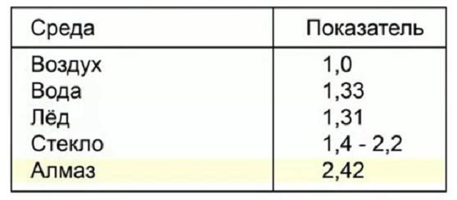
Optical density of substances
In addition to the fact that this parameter is a constant value, it also reflects the ratio of the speed of light in two substances. physical meaning can be displayed as the following formula:Another important indicator

Full internal reflection

Conclusion
 How to make a paper lamp with your own hands
 How to check the performance of the LED strip
 Newton directed a beam of sunlight through a small hole onto a glass prism. Getting on the prism, the beam was refracted and gave on the opposite wall an elongated image with iridescent alternation of colors - the spectrum. Experiment on the passage of monochromatic light through a prism:
 Newton placed red glass in the path of the sun's ray, behind which he received monochromatic light (red), then a prism and observed on the screen only a red spot from the ray of light. Experience in the synthesis (obtaining) of white light: First, Newton directed the sun's beam at a prism. Then, having collected the colored rays emerging from the prism with the help of a converging lens, Newton received a white image of a hole on a white wall instead of a colored strip. Newton's conclusions:- the prism does not change the light, but only decomposes it into components - light rays that differ in color differ in the degree of refraction; violet rays are most strongly refracted, red light is less strongly refracted - red light, which is less refracted, has the highest speed, and violet has the lowest, therefore the prism decomposes the light. The dependence of the refractive index of light on its color is called dispersion.


 Natural light is sometimes conventionally referred to as this. It is also called non-polarized.
 Polarizers used to analyze the polarization of light are called analyzers.